Assembly Instructions for the Shimano Nexus / Alfine 8 Speed Axle Sub-Assembly
Click here for more detailed, accurate and LARGE CAD dawings.
![]()
![]()
![]()
Assembly Instructions for the Shimano Nexus / Alfine 8 Speed Axle Sub-Assembly
Click here for more detailed, accurate and LARGE CAD dawings.
![]()
![]()
![]()
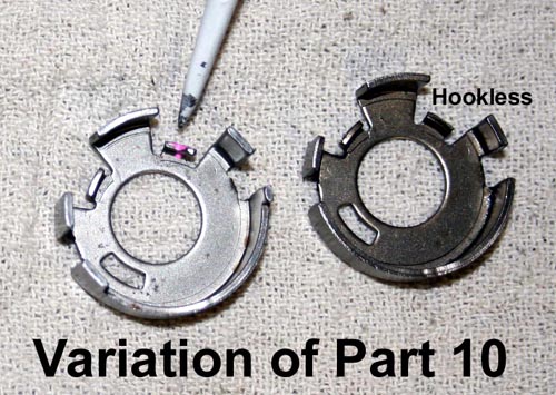
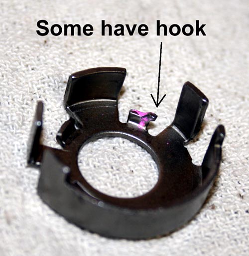
NOTE: There may be subtle variations of this axle unit. Some parts may not exactly match the drawings or pictures. It is possible to futher disassemble the axle unit to a bare axle, but it is not recommended or usually needed. Damage to the axle might result! If need be, pawls can be replaced without removing the actuator arm.

More on axle damage and failure.
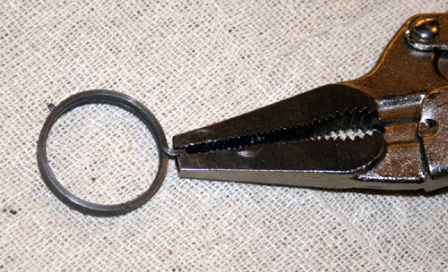
A word about tools: tools are only as skilled as the hands using them. This is an advanced procedure with no official manual. It is beyond most mechanic's abillity. That said, I cannot recommend any specific tool for any of the procedures you see below. It is mechanic's choice! You will see me using several different tools. There are several ways to do each procedure and several different tools you can use. It is even possible to do this entire procedure with just a stick! You may find the following useful. a vise, a small flat screwdriver, dental tool, pliers, needle nose Visegrips and gear oil.
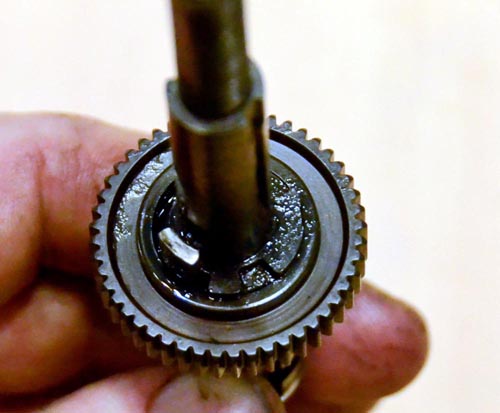
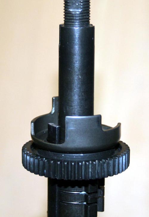
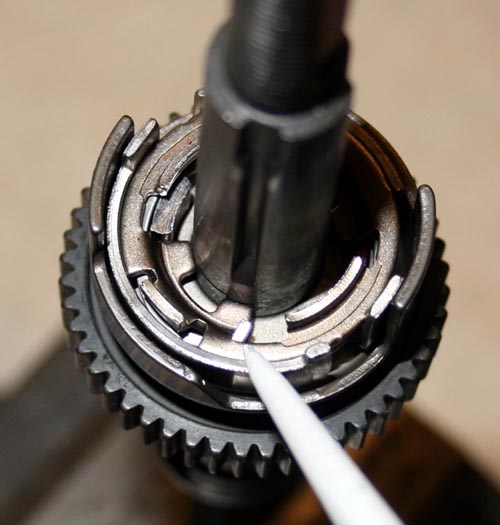
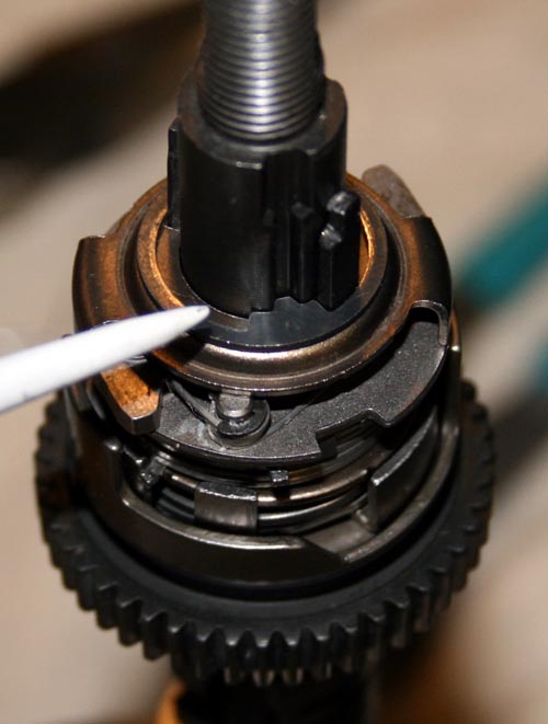
1. Clean and de-grease axle pawls and inspect for damage. They are easily replaced but parts must be obtained from a donor hub. Chipped or mushroomed pawls are caused by the indexing not being adjusted well. Usually a damaged, dirty or kinked cable is the cause. Always use metal housing caps (ditch the plastic ferrule Shimano supplies) and a quality cable and housing.
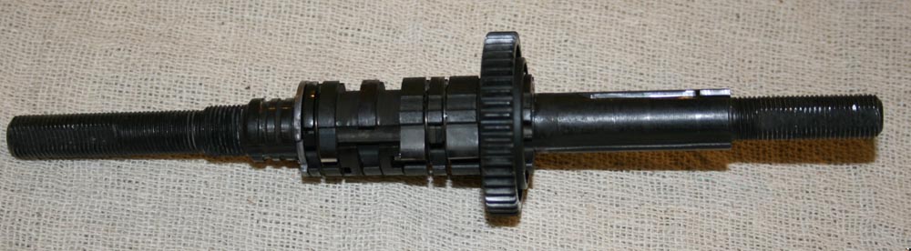
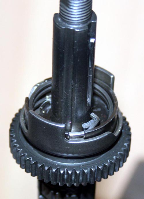
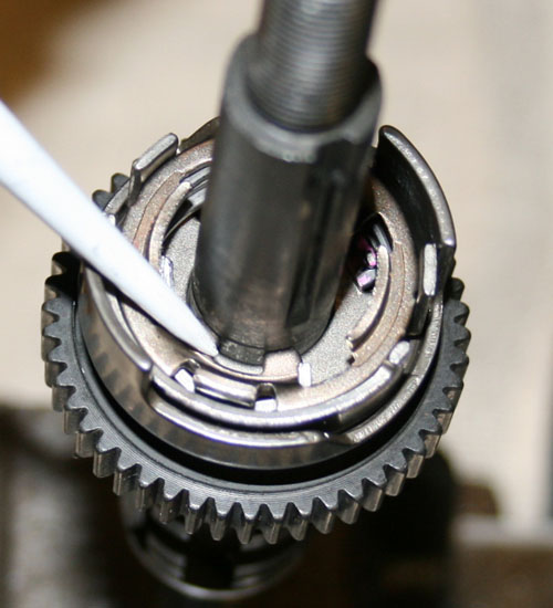
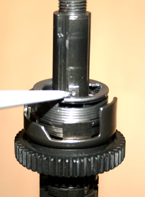
2. Oil the pawls and the other axle parts. Everything should rotate without resistance and you should see the pawls move in and out. Your axle should look like this:
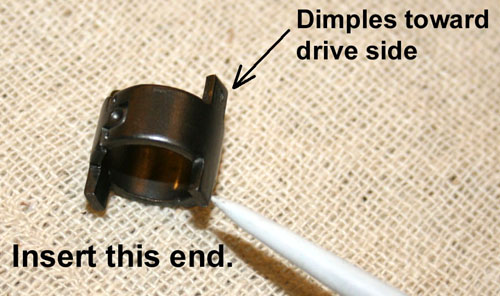
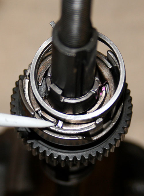
3. Install parts 11, 10 then spring 9.
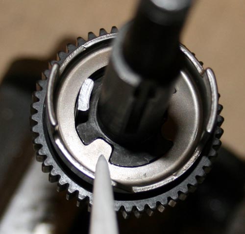
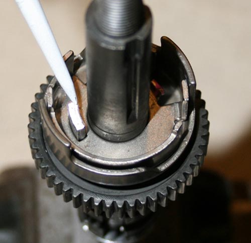
Note the spring hook location on part 10. It is easier to force spring 9 down into part 10 be for installing on the axle.
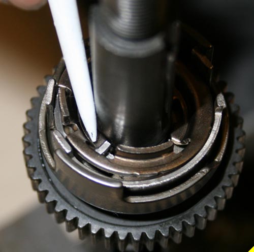
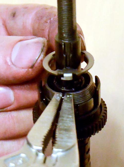
4. Hook spring 9 on part 8 and use part 7 as a tool to rotate counter-clockwise part 8 until it snaps down. No parts should be tilted and the parts should rotate without spring resistance. The pawls should work as in step 2. Make sure that spring 9 is not sticking up above part 10.
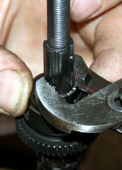
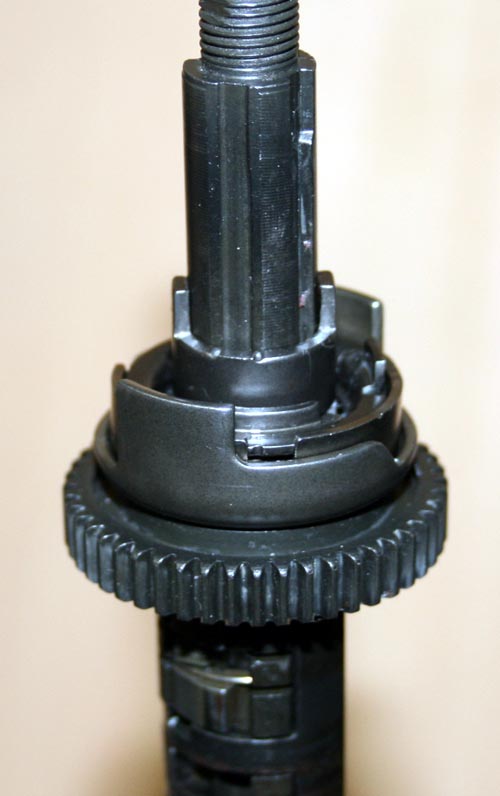
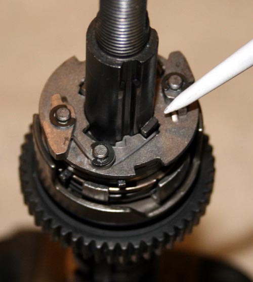
5. Install part 7. Tabs with divots point upwards. Opposite tabs engage notch in part 8.
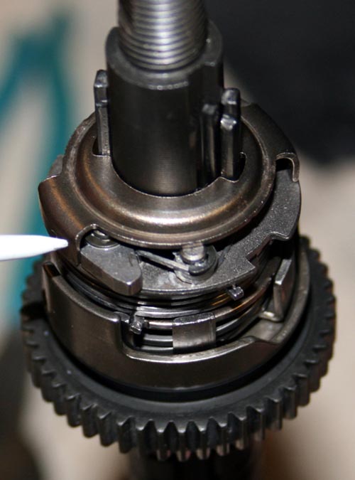
6. This is the hardest part! Hook short tab of spring 6 on part 8. Rotate spring clockwise about one turn and engage longer spring tab on part 5 as you install it. It is often easier to hook the spring 6 up first then work the coils over the shoulders of parts 5 and 8.
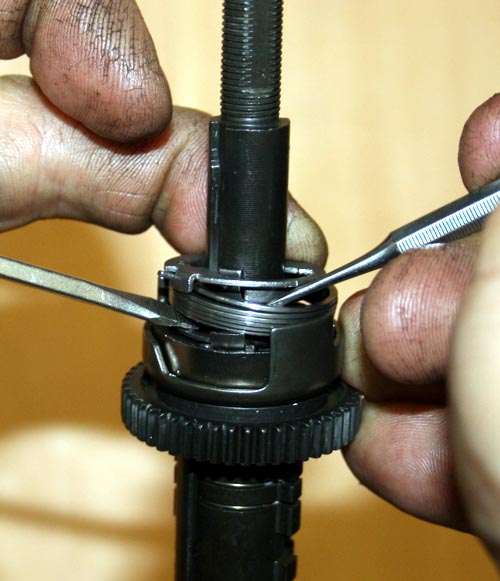
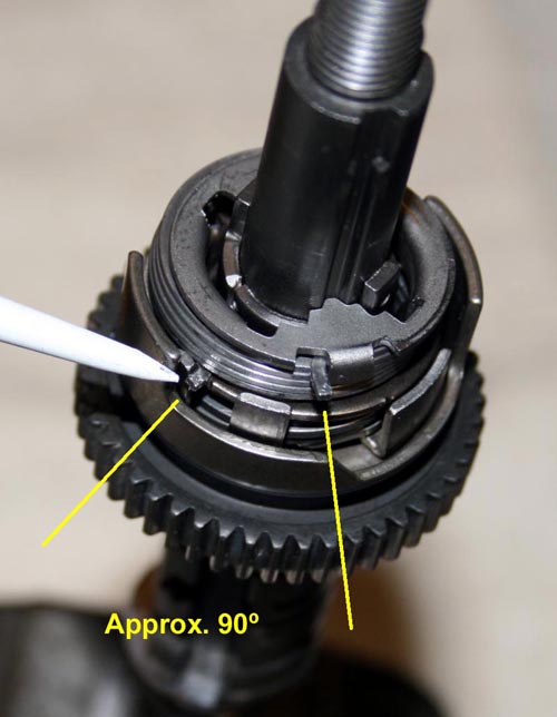
Parts 5 and 8 have collars that the spring coils must sit outside of. Everything will be flat again with the exeption of the spring. It is OK if it is tilted a bit. Once the spring is installed make note of the spring hook locations. They should be about a 90 degrees apart.
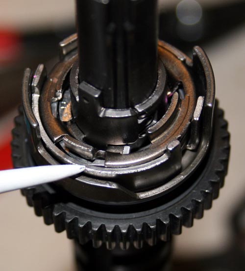
7. Install part 4. Spring ends point down and engage divots on the tabs of part 7.
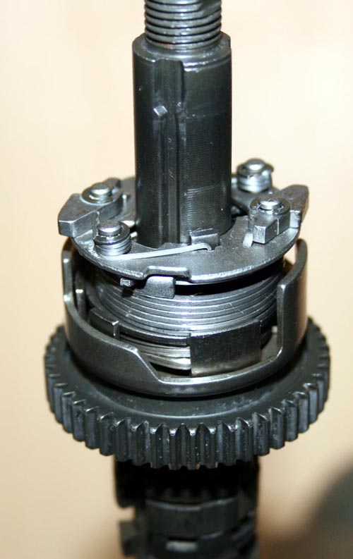
8. Install part 3 short tabs down. The short tabs of part 3 will push on the divot tabs of part 7 as part 3 is rotated counter-clockwise.
9. Install part 2. The shoulder tabs will sit next to the small pawls of part 4 and cause them to retract when part 2 is rotated counter-clockwise.
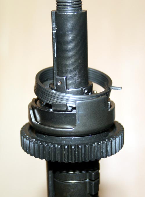
10. Install part 1. It should be necessary to rotate the longer tabs of part 3 counter clockwise to allow it to slide down.
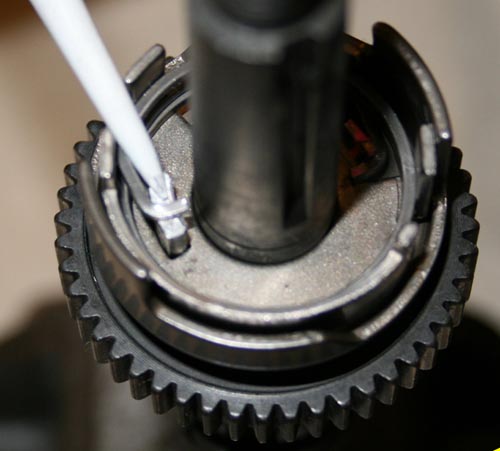
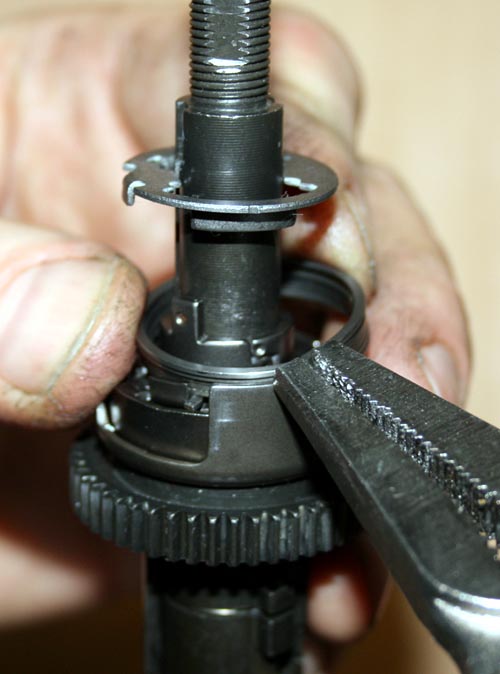
Test 1: Rotate the long tabs of part 3 with pliers and watch the axle pawls move in and out as in step 2. Only now there will be a strong spring force resisting the rotation from the main shift spring 9.
Test 2: hold the long finger like pawl engagement arm that encircles the axle with your thumb. Again move part 3 and notice that it moves but the spring tension higher from the pre-select spring 6. Part 10 and spring 9 inside it will not rotate.
![]()
Special thanks to JD Smalley for drawing the CAD diagrams and to John S. Allen for loaning me a complete axle unit.
Photos by Janice Butler and Danny McMillin. Hand model: Aaron Goss.